Hardware
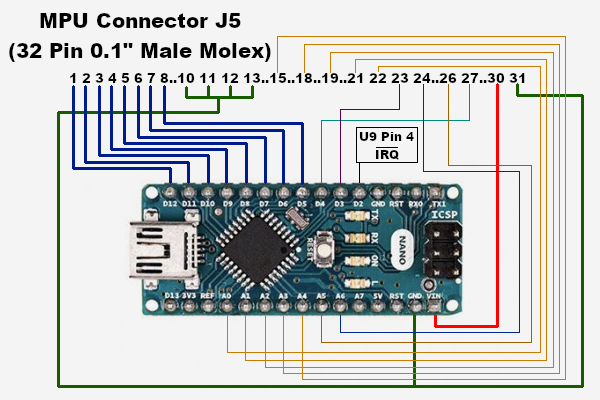
Interfacing the Arduino Nano to the MPU is really easy using the J5 connector on the board. The J5 connector is at the top of the board and it was originally meant as a diagnostic port. It contains access to all the lines needed except for the IRQ line. The lines used by this project are the following (J5 Pin # in parentheses, and followed by the hookup to the Arduino Nano Pin):
- Ground (31) - Nano GND
- +5V (30) - Nano VIN
- Theta 2 - clock (27) - Nano Pin 4
- VMA (26) - Nano Pin A5
- HLT (24) - Nano Pin A6
- R/W (23) - Nano Pin 3
- A0 (22) - Nano Pin A0
- A1 (21) - Nano Pin A1
- A3 (19) - Nano Pin A2
- A4 (18) - Nano Pin A3
- A7 (15) - Nano Pin A4
- D0 (8) - Nano Pin 5
- D1 (7) - Nano Pin 6
- D2 (6) - Nano Pin 7
- D3 (5) - Nano Pin 8
- D4 (4) - Nano Pin 9
- D5 (3) - Nano Pin 10
- D6 (2) - Nano Pin 11
- D7 (1) - Nano Pin 12
In addition, I ran a jumper from the CPU socket pin 4 (IRQ line) to the Arduino Pin 2, and I ran jumpers to connect J5 Pins 10, 11, 12, and 13 (A12-A9) to ground so I could guarantee that I was only accessing the PIA chips.
This project only accesses the MPUs PIA chips (U10 & U11). It doesn't use or need the RAM or ROM on the MPU board.
Wiring diagram: